The architecture of the Internet is based on the assumptions that network nodes are continuously connected, bit error rates are low, and data links are symmetric or bidirectional. However, in certain contexts, such as space or military environments, these conditions cannot always be guaranteed.
This post explain Delay and Disruption Tolerant Networks (DTNs), a networking approach designed for extreme conditions, where connections are unstable, delays are significant, or networks break frequently. We’ll then explore the main security issues and attacks against DTNs and show a practical simulation of both the normal and attack operations with a Python project (available here).
Classic Internet design works well when the following assumptions are usually true. DTN exists because in some environments those assumptions are usually false:
- Existence of an end-to-end path for the whole communication session
- Retransmission based on timely feedback from data receivers is an effective means for repairing errors for reliable communications
- Expected loss is relatively small
- Everyone supports TCP/IP protocols
- Picking a single route is usually sufficient
DTN is a digital communication technology designed to ensure reliable data delivery even when round-trip times are highly variable and/or very long.
Delays in communication can occur for several reasons, including:
- Long distances between the sender and receiver (e.g. transmissions between Mars and Earth)
- Obstructions or interference affecting the communication path (e.g. a planet temporarily blocking the line of sight)
How DTNs work
DTN operational principles can be summarized in three steps:
- Store: when a node generates or receives a packet (bundle) for an unreachable destination, it stores the information received in persistent storage.
- Carry: wait until a communication opportunity emerges, either when the node moves within range of another DTN node or when a scheduled contact time arrives.
- Forward: when contact occurs, the node transmits the bundle to the neighbouring node, which becomes responsible for continuing the delivery process.
This process repeats at each hop until the bundle reaches its destination or expires.
As we can see, it is completely different from “common” Internet routing, where if no path exists, packets are immediately dropped.
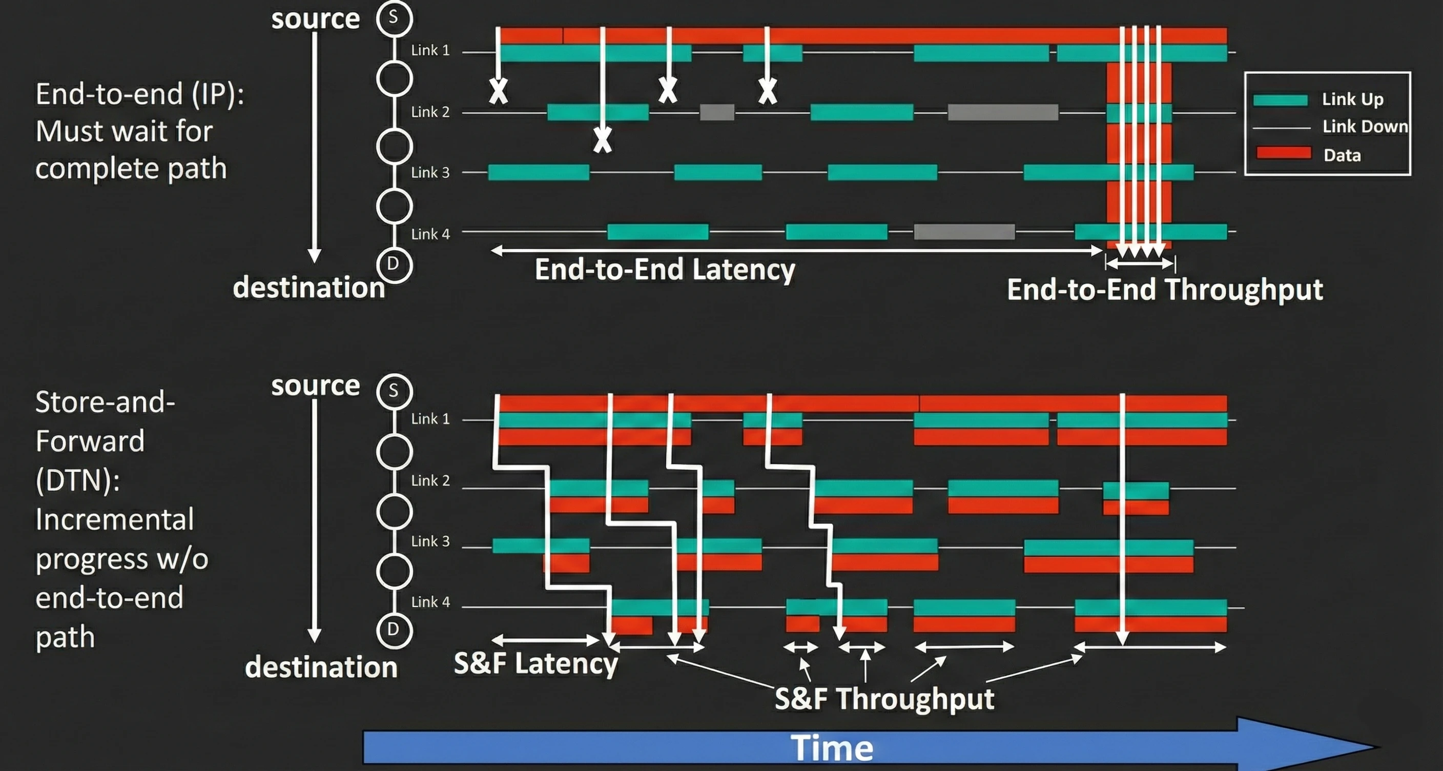
The figure below compares traditional end-to-end IP delivery (top) with DTN store-and-forward delivery (bottom) over four intermittent links between a source (S) and destination (D). In a normal end-to-end Internet (IP) approach, the sender can only succeed when there is a complete, continuous path from source to destination at the same time. If any hop is missing, transmission fails and must wait, so delivery is delayed until all links line up together.
With DTN store-and-forward, data is allowed to move in stages. Each time a temporary connection becomes available, the bundle is forwarded to the next node, then stored there until the next opportunity appears.
The Bundle Protocol Architecture
The Bundle Protocol (RFC 9171) is the overlay protocol sitting between the application layer and lower-layer transport protocols (TCP, UDP, LTP, or even non-TCP).
Let’s start by identifying the actors of this protocol. We can define a DTN node as the engine that sends and receives data using the bundle protocol. Each node belongs to one or more DTN endpoints, which are logical groupings of nodes that represent destinations. Each endpoint is uniquely identified with an Endpoint Identifier (EID). Additionally, the protocol introduces the concept of a Node ID, which is a specific EID that uniquely identifies a single node. While nodes typically have IDs, the protocol also supports anonymous bundles where the source is identified as the “null endpoint”.
A bundle is the fundamental data unit forwarded by DTN nodes. Unlike traditional internet packets, bundles are encoded using CBOR (Concise Binary Object Representation), which allows for efficient serialization. A bundle consists of a sequence of blocks:
- Primary Bundle Block: this is the immutable header of the bundle. It contains the essential routing information, including the destination EID, source node ID, report-to EID, creation timestamp, and lifetime (TTL). Once created, the data in this block must not change while in transit.
- Canonical Bundle Blocks:
- Payload Block: the container for the actual application data (the ADU).
- Extension Blocks: these provide additional metadata or hop-specific instructions. Examples include the Previous Node block (tracking where the bundle just came from), Bundle Age (tracking time in transit for nodes without synchronized clocks), and Hop Count (to prevent routing loops).
- Security Blocks: these blocks (Integrity Blocks and Confidentiality Blocks) provide the mechanism for data integrity and confidentiality.
The entire bundle is represented as a CBOR length array. It starts with the Primary Block, follows with other blocks, and is explicitly terminated by a CBOR ‘break’ code.
Group Semantics and Contact Models
Since the time windows to transfer data may not be long enough to send the entire storage content, the protocol relies on Lifetime and Retention Constraints. The Bundle Protocol relies on the Creation Timestamp and Lifetime fields in the Primary Block to manage storage retention. These fields define exactly how long a bundle is useful; once a bundle’s age exceeds its lifetime, nodes are expected to delete it to free up storage resources.
These lifetime and retention rules become even more important once we move beyond one-to-one traffic. If a bundle targets a group of receivers, storage isn’t just a buffer for delay; it can be the thing that makes group delivery possible at all.
When an EID refers to an endpoint containing more than one DTN node, DTN supports two “group delivery” styles:
- Anycast: deliver the bundle to one node in the group. This minimizes resource usage because the network only needs to deliver the bundle once.
- Multicast: deliver the bundle to all nodes in the group (DTN treats broadcast as a form of multicast).
Multicast is especially interesting (and challenging) in DTN because group membership can be time-shifted.
In low-delay networks, multicast typically assumes near-real-time membership: if you joined recently, you receive what is being sent now (or shortly after). DTN breaks that assumption. A node might join the group much later, because it was disconnected, asleep, or out of contact, and still want to receive bundles that were sent to the group during an earlier time interval.
This leads to temporal group semantics: the network may need to store multicast traffic long after senders have stopped transmitting, so that late, connecting members can still receive the data. In practice, this means DTN multicast can require persistent storage, replay, and delivery guarantees across long gaps in connectivity.
Addressing and group semantics answer who should receive a bundle. The next bottleneck in DTNs is when we’re even able to transmit. Since links appear and disappear, DTN routing starts from a more basic primitive than “interfaces”: the notion of a contact.
A contact is a time interval when an edge has positive capacity and stable characteristics. Given the possible long waiting time (e.g. if sending a bundle from a Deep Space Network (DSN)) we need to consider how predictable these contacts are and what we need to do to make them happen.
DTN architecture introduces several types of contacts:
- Persistent Contacts
Persistent contacts are links that are effectively always available: no special “start” action is needed to bring the connection up, and nodes can assume the contact exists continuously (or for very long periods). This is the simplest case for routing because the path is stable and the main concerns are bandwidth and delay, not whether the link will appear. - On-Demand Contacts
On-demand contacts are not always active, but they become persistent-like once initiated: some explicit action is required to trigger the contact (e.g. placing a call, powering up a link, requesting a session), and the contact remains usable until it is terminated. In DTN terms, the network must treat “contact establishment” as a step that can fail, take time.
Example: A lunar lander powers on its directional antenna and initiates a scheduled “session request” to a lunar relay when it needs to transmit a stored science batch; once the link is established, it behaves like an always-on connection until the lander ends the session to save energy. - Intermittent - Scheduled Contacts
Scheduled contacts are intermittent links that exist only during agreed time windows with a known (or planned) duration. Nodes can build a contact plan from known orbital passes, antenna pointing windows, or prearranged communication sessions. Because propagation delay can be large, the idea of “the same time” is delay-dependent: the event of “contact starting” is not detected simultaneously at both ends if the signal travel time is significant. - Intermittent - Opportunistic Contacts
Opportunistic contacts are intermittent links that appear unexpectedly (not on a fixed schedule). Nodes discover them at runtime, often via beacons/advertisements, and the contact duration is uncertain.
Example: Two satellites in different constellations come into cross-link range due to an alignment; one satellite detects the other’s beacon and immediately forwards queued emergency telemetry bundles during the short, unplanned link. - Intermittent - Predicted Contacts
Predicted contacts are not fixed appointments, but probabilistic expectations based on past observations or contextual information. The system estimates likely contact times/durations (with some confidence level) and may choose routes that rely on these predictions when confidence is high enough. This is a trade-off: better throughput and earlier forwarding versus the risk that the contact will not occur as expected.
Routing Strategies
Contacts tell us what opportunities exist, their timing, duration, and capacity. Routing (and forwarding policy) is the step that turns those opportunities into decisions: which queued bundles go out on which contact, and which next hop gives the best chance of delivery.
In DTNs, routing is less about “what’s the shortest path right now?” and more about “what path will exist in the future, and will it have enough capacity when it does?”. Because links are time-bounded and asymmetric, every routing algorithm ends up balancing the same core constraints: time (when a contact opens), delay (including one-way light time), volume (how many bytes the contact can carry), and risk (the chance the contact never happens or ends early). Different environments require the adoption of different routing families:
- Planned / contact-plan routing (scheduled DTNs)
This is the “space and infrastructure” case: you have a contact plan (built from orbital passes, antenna schedules, known relays) and you route by treating time as a first-class dimension. Here the primary algorithm is Contact Graph Routing (CGR), because it can exploit predictable contacts and make repeatable, optimized decisions. - Opportunistic / encounter-driven routing (mobile or unpredictable DTNs)
Nodes discover each other at runtime and forward based on who they meet. These algorithms often trade bandwidth/storage for delivery probability via replication:- Single-copy (low overhead): e.g. First Contact forwards to the first viable neighbour (basically a controlled random walk).
- Multi-copy / flooding (high delivery probability, high cost): e.g. Epidemic replicates to every new contact.
- Bounded replication (middle ground): e.g. Spray and Wait limits copies to L and then waits for a good opportunity.
- Priority/queue-aware replication: e.g. MaxProp still replicates, but prioritizes which bundles to transmit first and which to drop when storage is tight.
- Prediction-based routing (probabilistic DTNs)
Sitting between the two algorithms just seen, these schemes don’t require a fixed schedule but do use history/context to estimate good next hops (e.g. “I meet node X often, so X is a good carrier”). They’re useful when contacts are repeatable but not strictly scheduled.
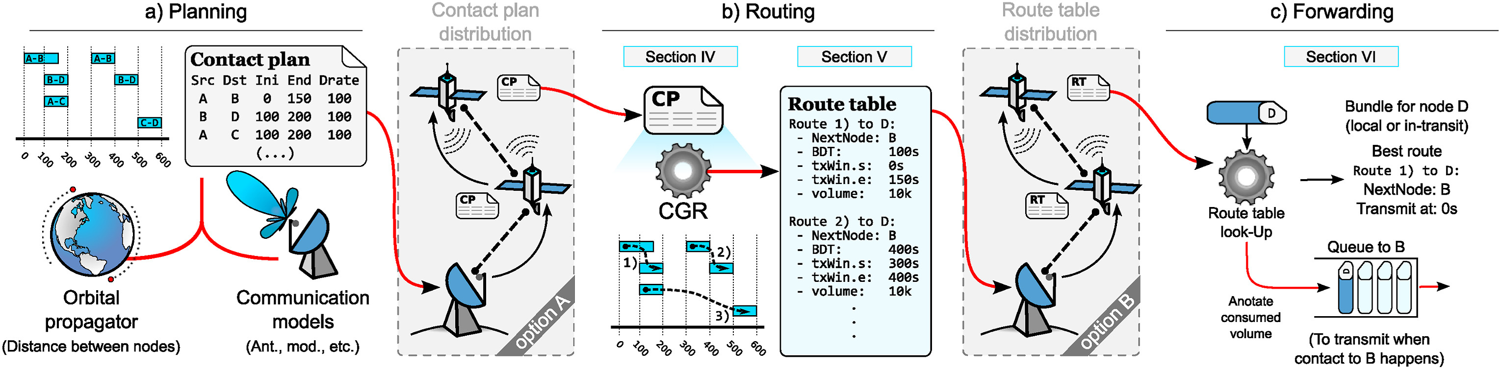
As said before, Contact Graph Routing (CGR) is one of the most used routing algorithms. It assumes we have (at least) a partial contact plan, and it turns that plan into a time-dependent graph: each contact is a directed edge annotated with a start time, end time, data rate, and one-way light time (OWLT). Routing then becomes a “shortest path” problem, except the cost is usually earliest delivery time (or a policy-weighted variant), and edges can only be used inside their time window.
At a high level, when a bundle is ready to move, a node follows a similar behaviour:
- Build the candidate graph from the plan
The node considers all future contacts it knows about from now until the bundle’s lifetime would expire. Contacts that end before the bundle could even be transmitted are ignored. - Account for capacity: remaining contact volume matters
Each contact has a total volume budget:contact_volume = data_rate × (end_time − start_time).But CGR doesn't assume the whole volume is free: it estimates how much is already committed to previously scheduled traffic, leaving a residual volume. If the residual volume can't fit the bundle (or the portion you plan to send), that contact is treated as "not currently usable" for that bundle. - Run a time-aware path search
CGR finds the best route by treating the “cost” as when the data will arrive, not how far it travels, so each possible link is evaluated based on the earliest time your bundle can reach the next node:- you can only depart at or after the contact start time
- if you arrive at the transmitting node early, you may have to wait until the contact opens
- once sent, delivery to the far end happens after the OWLT (plus any local transmission time assumptions) The algorithm explores sequences of contacts and finds a route that can deliver the bundle the soonest (or according to local policy: earliest arrival, earliest arrival with margin, minimum hops among ties, etc.).
- Pick the next hop (and schedule it)
CGR’s output is typically not “the whole path”, but the best next-hop contact (and often a small set of backup routes). The bundle is then placed into the outbound queue associated with that contact and stored until the contact opens. - React when reality diverges from the plan
Even “scheduled” space contacts can fail (pointing issues, DSN changes, weather at a ground station, power constraints). If the contact is missed, its residual volume is exhausted by higher priority traffic, or the plan is updated, the node simply re-runs CGR and chooses a new next hop.
This is why CGR works well with DTNs: it is based on the fact that “the route” is a sequence of future transmission opportunities, and it makes forwarding decisions that are explicitly constrained by time windows and capacity.
Fragmentation and Reassembly
Even when we decided how and when to send bundles, DTN routing faces a practical limit: the contact volume (the total data that can be moved during a contact) may be smaller than the bundle we want to send, or the contact may end unexpectedly.
If we treated bundles as indivisible objects, a partially transmitted bundle could force costly retries and waste precious contact time. The protocol addresses this with Fragmentation and Reassembly, whose goal is to keep contacts fully utilized while avoiding retransmission of data that has already made progress.
Fragmentation improves transfer efficiency in two main ways: it ensures that short or variable contacts are fully used, and it avoids retransmitting portions of bundles that were already forwarded successfully. The standard defines two complementary fragmentation approaches:
- Proactive Fragmentation
A node intentionally divides a block of application data into multiple smaller parts before sending, transmitting each part as an independent bundle. The final destination is responsible for collecting these incoming pieces and reassembling them back into the original Application Data Unit (ADU).
This approach is mainly used when contact volumes are known or predicted in advance (e.g. via a contact plan). By shaping bundle sizes to the expected contact volume, the sender reduces the chance that a contact ends mid-transfer. Crucially, this is the preferred method when using security blocks (BPSec), as it allows each individual fragment to be independently signed and encrypted at the source, ensuring full security verification remains possible at the destination. - Reactive Fragmentation
The process occurs after a transmission attempt has already begun, specifically when a bundle is only partially transferred before the link breaks.
The previous-hop sender learns that only a portion of the bundle arrived. It then creates a new bundle fragment containing only the remaining, untransmitted portion of the payload. This new bundle is treated as an independent entity and may even be routed through a different next hop if the topology changes.
While efficient for data volume, reactive fragmentation poses significant challenges for security. Because security blocks (which we will discuss in detail in the next section) like Block Integrity Blocks (BIB) and Block Confidentiality Blocks (BCB) typically protect the entire payload, splitting a bundle mid-transit invalidates the cryptographic signatures and authentication tags. Therefore, when data integrity or confidentiality services are required, reactive fragmentation is explicitly incompatible with BPSec. The standard requires that a BIB or BCB must not be added to a bundle if it is already a fragment. Security must be applied to the complete bundle before any proactive fragmentation occurs.
Regardless of which method is used, the protocol requires that reassembly typically happens at the final destination, though the standard allows it to occur at intermediate nodes on the path if necessary. This simplifies routing, as intermediate nodes process fragments exactly like any other bundle, without needing to buffer data or wait for missing pieces. Once all fragments arrive at the destination, they are logically reassembled together to recreate the original payload for the application.
Reliability and Diagnostics
Fragmentation techniques that we’ve just seen can help to short contacts efficiently, but it doesn’t automatically make delivery reliable. For mission-critical traffic, we often want stronger guarantees, so DTN adds reliability above intermittent links instead of assuming the network can provide it end-to-end.
While the core protocol operates on a “best-effort” basis, critical operations in space or military environments often require higher reliability guarantees. In the modern specification, this is handled through architectural decisions rather than a simple flag in the bundle header:
- Custody Transfer via Encapsulation
When a node acts as a “custodian”, it accepts responsibility for the bundle’s safe delivery. Instead of just forwarding the data, the custodian encapsulates the original bundle inside a new one (using Bundle-in-Bundle Encapsulation). It commits the bundle to persistent storage and keeps retransmitting it until it receives a signal that another node closer to the destination has taken over custody. This effectively moves the “retransmission loop” from the original sender to intermediate nodes. - Convergence Layer Reliability
For many deployments, reliability is delegated down to the Convergence Layer Adapters (CLAs). For example, when using the TCP Convergence Layer (TCPCL), the responsibility for ensuring a bundle successfully crosses a specific hop lies with the underlying transport connection. The Bundle Agent only considers the bundle forwarded once the underlying adapter confirms the transfer is complete.
Once we introduce custody and hop reliability, we also need visibility: where is the bundle now, did it move, did it expire, and who has responsibility? That’s what the reporting flags provide, a lightweight feedback channel that works even when “real-time” doesn’t.
To track the progress of these bundles, the sender can set specific Bundle Processing Control Flags in the Primary Block. The standard defines five specific flags designed for feedback and diagnostics:
- Report When Bundle Received
This diagnostic option requests a Bundle Reception Status Report each time a sent bundle arrives at any DTN node (not just the final destination). “Received” here means the node has accepted the bundle from the incoming link into its local processing. This is mainly useful for troubleshooting and visibility, letting the sender trace the bundle’s path hop-by-hop. - Report When Bundle Forwarded
This diagnostic option requests a Bundle Forwarding Status Report when a sent bundle leaves a DTN node after forwarding. “Forwarded” means the node has scheduled or performed transmission of the bundle on an outgoing link. This helps identify where bundles may be stalling: if you see reception reports but not forwarding reports from a node, that suggests queueing, contact issues, or policy constraints at that node. - Report When Bundle Delivered
This option requests a single Bundle Delivery Status Report once the payload has been delivered to its intended recipient node. The key idea is that the report corresponds to the protocol’s notion of delivery at the destination node, not necessarily that the receiving application has processed the data. - Report When Bundle Deleted
This diagnostic option requests a Bundle Deletion Status Report when a sent bundle is deleted at a DTN node. Deletion can happen for technical reasons such as expiration of lifetime (TTL), storage exhaustion, or administrative action. This report is especially useful because it signals a likely failure mode: if a bundle is deleted before reaching the destination, the sender can learn where it was dropped and correlate that with network conditions. - Acknowledgement by Application
This option requests an Acknowledgement Status Report when the receiving application explicitly acknowledges the data. Unlike the “Bundle Delivered” report, this is triggered only by application action. It is intended for cases where the destination application acts as a gateway or proxy and wants to signal that a higher-level operation (outside DTN itself) has completed successfully. 6. Status Time Requested
This flag requests that all status reports generated for this bundle include a timestamp indicating exactly when the status event occurred.
We can summarize the data-flow that we’ve seen in this entire paragraph, in the same order a bundle “lives” through the system. We started with structure: the Bundle Protocol defines what gets stored and forwarded, and how endpoints are named with EIDs and node IDs. With that in place, the sender chooses a send policy: for group endpoints, anycast means “deliver to one member” while multicast means “deliver to all”, with DTNs adding the complication of time-shifted group membership that can force long-term retention.
Next comes contact, which defines when transmission opportunities exist (persistent, on-demand, scheduled, opportunistic, or predicted) and how much capacity they likely have. Given those opportunities, the routing/forwarding algorithm decides when and where to send next, from plan-driven CGR (time-aware paths over scheduled contacts and residual volume) to encounter-driven replication for opportunistic settings.
When the next hop might not have enough contact volume to carry a whole bundle, fragmentation (proactive or reactive) adapts bundle sizes so partial contacts still produce progress instead of forcing full retries, while also interacting with security constraints.
Finally, delivery options define the reliability and feedback from the bundle layer: mechanisms like custody transfer and hop reliability via convergence layers improve delivery assurance, and status reports provide visibility so the sender can tell what happened despite long delays and disruptions.
DTN Security
The different architectural paradigm of DTNs brings new security challenges; common security architectures are not designed for a network that stores your data on someone else’s disk, follows unpredictable paths, and is handled by nodes that are offline from your PKI for long periods of time.
In addition to “normal delivery”, secure DTN stacks generally expose security services including:
- Confidentiality: the Application Data Unit (ADU) or specific metadata must be kept secret from everyone except the source and members of the destination endpoint ID (EID).
- Integrity and Authenticity: ensures that data has not been modified in transit and allows the receiver to verify the identity of the source. This protects critical metadata and the payload itself.
Bundle Protocol Security (BPSec)
The Bundle Protocol Security (BPSec) specification introduces secure bundles by adding security blocks to the bundle itself.
Unlike previous iterations of the protocol, BPSec removes the distinction between “payload” security and “extension” security. Instead, it defines generic security blocks that can target other blocks in the bundle. The security blocks introduced are:
- BIB - Block Integrity Block
Provides integrity and authentication for a target block (which can be the payload block or any extension block). A BIB contains a security result (like a digital signature or a MAC) generated by the security source. Multiple BIBs can be attached to a bundle. For example, the source node might sign the payload, while a forwarding gateway might sign an extension block containing routing instructions. When a node receives a bundle with a BIB, if it possesses the necessary key material, it can verify that the target block has not been tampered with. - BCB - Block Confidentiality Block
Provides confidentiality for a target block via encryption. When a BCB is applied, the content of the target block (e.g. the payload) is encrypted in-place, and the BCB itself carries the necessary parameters (like initialization vectors or ephemeral keys) and authentication tags. Similar to BIBs, a BCB can target the payload or extension blocks. This allows, for example, a bundle to have an encrypted payload, readable only by the final destination, while keeping extension blocks plaintext for intermediate routing.
It’s important to note that BPSec does not provide enforced hop-by-hop authentication. While an intermediate node could theoretically verify a BIB if it has the key, BPSec does not require this.
Main DTN Attacks
BPSec, with the implementation of security blocks, allows us to protect against the main attacks related to confidentiality, integrity, and authenticity. However, as with the majority of systems, there are other attacks that remain possible:
- Traffic dropping
An on-path node (“blackhole”) can intentionally drop bundles, preventing delivery. BPSec can help to detect that a bundle was protected (ensuring data wasn’t spoofed), but it cannot force an uncooperative forwarder to actually relay traffic. This is one of the most powerful attacks against DTNs because long delays and intermittent connectivity make it hard to distinguish “dropped” bundles from those still in transit.
Typical countermeasures are redundancy (multi-path forwarding / replication), which increases total traffic and cost, and using trust boundaries to avoid untrusted relays. - Resource exhaustion - DoS
Attackers can attempt to exhaust scarce DTN resources (buffer space, CPU, battery, contact time) by injecting many bundles, very large bundles, or bundles crafted to be expensive to process.
BPSec mitigates this by allowing nodes to enforce “verify-before-store” policies, where bundles with invalid BIBs are rejected before they consume long-term storage. - Misdelivery
A bundle can be delivered to the wrong application or endpoint due to misconfiguration, compromised routing state. BPSec can authenticate and protect the integrity of the payload via BIBs, ensuring that even if the bundle arrives at the wrong place, the unauthorized recipient cannot modify it without detection, and (if BCBs are used) cannot read it.
Mitigations include strict endpoint authorization policies and careful EID management. - Replay and duplication attack
Attackers can re-inject previously valid bundles or intentionally duplicate traffic to waste storage and bandwidth, or to trigger repeated application actions. BPSec integrity/authentication does not automatically imply freshness: a perfectly valid, signed bundle can be replayed unless the receiver enforces replay protection.
Common mitigations involve security contexts within BPSec that utilize timestamps, sequence numbers, or anti-replay counters within the BIBs/BCBs to allow receivers to detect and discard old traffic. - Tampering
BPSec makes tampering with target blocks detectable, if the receiver verifies the relevant BIBs. However, attackers may still tamper with: (1) mutable data in Extension Blocks (like Hop Count) or the fact that fragments modify metadata like data length, (2) unprotected extension blocks that represent a target not covered by a BIB, or (3) the environment itself (clock manipulation).
Mitigations include strict policies that require specific blocks (like the payload) to be BIB-protected before processing. - Information leakage via security failure reporting
Diagnostic behaviour, such as status reports or security failure notifications, can unintentionally reveal sensitive information. For example, a report might leak which security policy is enforced or which keys are recognized. In hostile environments, this turns error reporting into an oracle that helps attackers refine their attempts.
Mitigations include minimizing detail in failure reports, encrypting reports using BCBs, and carefully scoping who is allowed to receive security status information.
As we can see, most of these mitigations come with a real operational cost: more computation for verification, more storage for caches and replay tables, more bandwidth for redundancy and reporting, and more complexity in policy management and key distribution.
In a DTN security is a balancing act between risk reduction and sustainability.
Case Studies
Now that we have an overview of how DTNs work, we can discuss two real-world applications of these systems. To allow a better understanding of the concepts that we discussed above, a Python CLI script with a Terminal User Interface (TUI) is available here, showing an interactive simulation with two different scenarios.
Space Communications
The Jet Propulsion Laboratory selected the EPOXI spacecraft for what would become the first deep-space demonstration of DTN technology. EPOXI was ideally suited for the experiment; the spacecraft was in a cruise phase heading toward comet Hartley 2, meaning operators could use it for testing without affecting the primary mission.
On October 18, 2008, JPL engineers uploaded the ION (Interplanetary Overlay Network) software, NASA’s implementation of DTN protocols, to the spacecraft’s backup flight computer.
JPL created an 11-node network where the spacecraft itself functioned as a router, a relay station that would receive data, store it, and forward it when the opportunity arose. Images were sent from ground control to the spacecraft and then automatically relayed back to different ground stations.
Over those 27 days, the experiment moved 292 images, approximately 14.5 megabytes of data, through the network. Every high-priority image was successfully delivered without a single corruption. Some low-priority images were discarded when their time-to-live expired before sufficient contact opportunities arose, but this was intentional, a feature of DTN’s ability to prioritize critical data over less important transmissions when network capacity was limited.
Military Communications
Military operations often take place in environments where communications are unreliable; think of platoons moving through mountains, dense urban areas, or under enemy jamming. In these scenarios, continuous end-to-end network links can’t be guaranteed. Delay/Disruption Tolerant Networking has been actively tested and deployed to make battlefield networks more resilient. One real-world example is the U.S. Army’s experiments with DTN-enabled tactical radios, spurred by a DARPA program aimed at preventing data loss in the field.
Imagine a convoy of Army vehicles and dismounted soldiers spread across a rural valley. They rely on radio networks for situational awareness, but terrain and obstacles (hills, buildings, even armored vehicle hulls) regularly block signals. In a conventional network, if a squad member goes behind a hill, any data they were sending (a position report or request for support) would simply drop and never reach the command post. DTN changes this paradigm.
References:
- RFC4838: www.rfc-editor.org/rfc/rfc4838
- RFC9171: https://datatracker.ietf.org/doc/html/rfc9171
- RFC9172: https://datatracker.ietf.org/doc/html/rfc9172
- https://ntrs.nasa.gov/citations/20120006508
- https://ntrs.nasa.gov/citations/20150014735
- https://youtu.be/2RHzIxbBJgo
- https://youtu.be/XTmYm3gMYOQ
- https://wikipedia.org/wiki/Routing_in_delay-tolerant_networking
- www.nasa.gov/wp-content/uploads/2023/09/dtn-tutorial-v3.2-0.pdf
- https://youtu.be/6YlMPh0EB_w
- https://doi.org/10.1109/SPACOMM.2009.39
- https://doi.org/10.1016/j.jnca.2020.102884
- https://doi.org/10.1007/978-3-319-16549-3_3